Test Configurations

Application Methods

A variety of applications with various installation configurations are possible and have been used in gas turbine engine testing. LG Tech-Link Global works with customers to support specific project requirements and develop good practices for new types of configurations, as needed.

LG Tech-Link Global

1. Max metal temperature measurement

Using a dental burr, EDM or additive manufacture, pockets are made directly in the material of the test article. A UCTS sensor is then inserted into the cavity and bonded in place with adhesive thermal cement. In some cases a thin metal foil or shim stock is spot welded over the cavity for extra protection. Applications have been performed in un-coated or coated (TBC or other) parts.
* Dimensions shown are for standard Installation, and can be modified.

Back to top

LG Tech-Link Global

2. Encapsulated surface temperature sensor

Due to logistic or physical constraints, users may choose to create an installation package that can be secured to the surface of the test part and removed more easily.  Although not ideal in terms of intrusion into the flow field, it may be the only option for obtaining much needed data.  A variety of approaches may be use to create “buttons” or capsules that are spot welded onto the surface or semi-embedded.  LG Tech-Link Global can work with you to help guide the design to optimize results.  One example is shown here.  In this sample configuration the UCTS is installed into a central chamber, which is then filled with thermal cement and covered with a shim. The capsule assembly is spot-welded to the surface of the part to be instrumented at the location of interest.  Simpler versions have been used.

Back to top

LG Tech-Link Global

3. Temperature sensor inserted

When measurement is required at a greater depth in the material that would make removal difficult; a wire, pin or screw is used with the sensor installed in a small cavity at the tip. This allows for measurement of temperature at a particular depth or to approach a coated or hard to reach surface from the opposite side.

Back to top

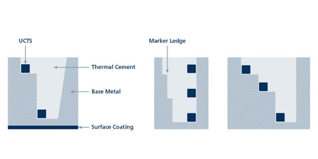
4. Gradient temperature measurement

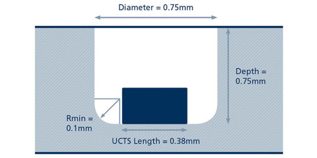
While there are a number of methods that allow for single point measurements on test articles there are fewer techniques available for gradient measurement in engine conditions. Variations of the ‘Stair-step’ or ‘Stacking’ cavity (shown right) allow for consistent placement of multiple UCTS, so that a good quality measurement of the max temperature at different depths through the wall can be taken. It also allows for measurement in close proximity to a coated wall surfaces without alteration to or intrusion into the coating itself.

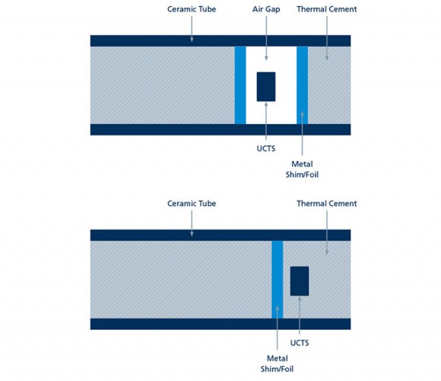
UCTS could also be used to measure conductive heat flow by using two sensing zones at the ends, separated by a thermal resistance layer with known conductive characteristics. The UCTS would act as a natural HEAT FLUX SENSOR if positioned along the lines of maximum temperature gradient.

Back to top

LG Tech-Link Global

5. Gas temperature measurement

Custom designed Temperature Rake with ultra-thin aerodynamic profile could be constructed using UCTS sensors. Small ceramic tubes installed with thermo-cement on blades and vanes have been used to get gas temperature and gas temperature profile information in the turbine environment.

Back to top

LG Tech-Link Global

6. Long duration testing

UCTS sensors have the ability to survive long duration testing in the real engine environment. Furnace and Engine Testing have shown that UCTS can operate for over 1500 hours at 2000°F. Total Test Times for some tests have exceeded 6 months. This robustness and flexibility makes it a good choice for Industrial Gas Turbine OEMs and for multi task tests of Aviation Gas Turbines.

Back to top